- Get link
- X
- Other Apps
A damping resistor r is connected to the secondary of each vt see figure 1 below if consumption downstream of the vt is not sufficient. Saturation curves were obtained for the vts of the three manufacturers and an emtp model was construc ted.

Glossary Basic Knowledge Crystal Units Murata

Parallel Resonance And Parallel Rlc Resonant Circuit

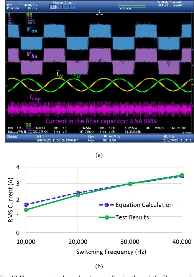
Figure 12 From Multi Domain Design Optimization Of Dv Dt
Influence of high inrush current and resulting distortion high stress on the capacitor reduces lifetime welding or fast wear off of the main.

Damping resistor calculation. Design tradeoffs are discussed. To avoid negative effects and to improve a capacitors lifetime adequate damping of inrush currents is highly recommended. Influence of damping resistance against the accuracy of pt measurements.
The model was actually quite simple in this case. This kind of damping method with series reactor expands the applicable range of resistance damping method. It determines whether or not the circuit will resonate naturally that is without a driving source.
Its analogous to a swinging pendulum friction will eventually stop the swinging. Damping is caused by the resistance in the circuit. But the practical effect of.
Figure 431 depicts the curve of the energy consumption of the damping resistor versus resistance during a single spark. Critical damping produces the simplest possible circuit and automatically works at any charge voltage. More resistance more damping.
In this case the resistors continuously absorb power as soon as the vts are energized. That is a resistor damping oscillations. Circuits which will resonate in this way are described as underdamped and those that will not are overdamped.
Additional criteria are derived that allow employment of these results in design of multiple section cascaded filters with damping. A critically damped circuit does not require protection because the capacitor voltage will never become negative. If the there is some resistance in the circuit say in the coil windings the energy in the oscillations will be converted to heat and the oscillations fade to nothing exponentially.
Damping to an ac grid stresses the capacitor similar to a short circuit. It can be seen that higher resistance results in higher energy consumption. When resonance appears the reactor reaches saturation prior to the pt so as to get the resonance suppressed.
Damping attenuation symbol a is measured in nepers per second. The existing design standard called for a damping resistor r0 of 60 ohms but this obviously had not provided enough damping to prevent the failure of 72 vt s. When the resistance is in the range of 0100 w the energy consumption sharply increases as the resistance increases.
With a damping resistor the effective output impedance is assumed to be 33 thus matching the line impedance. In this case while there is a step in the signal at the driver output point a the receive r side point b sees a very clean signal transition without any significant undershoot or overshoot. Damping of an input filter using a single resistor.
This procedure is employed to derive the equations governing optimal damping of several basic filter circuits. An under damped circuit requires protection for electrolytic capacitors.

8 Damping And The Natural Response

How Resistance In Coils Affects The Damping Of Oscillations

Solved E If We Were To Use Both The Inductor L 150h An

Damping Resistor An Overview Sciencedirect Topics

Rlc Circuit Wikipedia

Are You Using The Right Ct S And Pt S For Your Application

Damping Resistor Resistor Electrical Resistance And

Damping Resistor Pdf Resistor Electrical Resistance And

The Quick And Easy Way To Design Emi Filters Online

Estimation Of Damping Resistor In Mechanically Switched

Rlc Step Response

Passive Filter Design Concept Of Buck Regulators For Ultra
Comments
Post a Comment